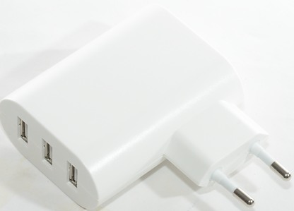
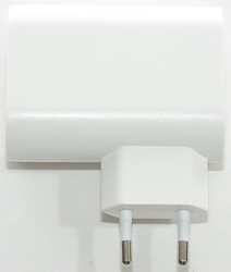
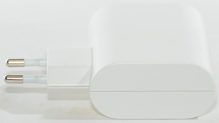
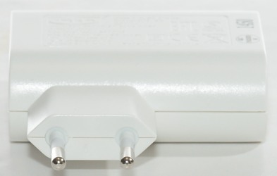
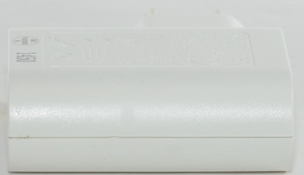
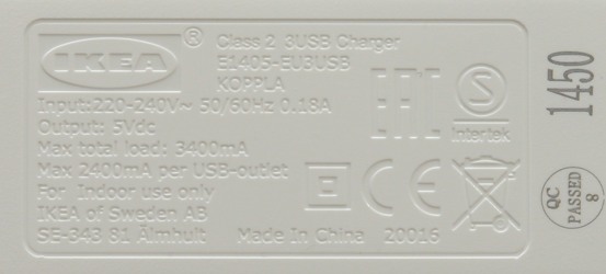
Ikea Koppla
Official specifications:
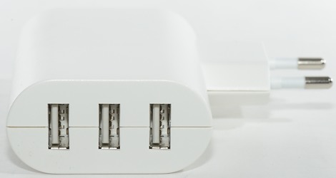
- USB ports: 3
- Total current output: 3400mA
- Port current output: 2400mA
I got it from Ikea
Measurements
- Power consumption when idle is about 0.03 watt
- Port ports has automatic coding up to Apple 2.5A
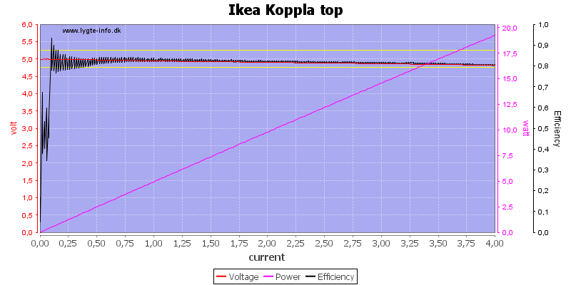
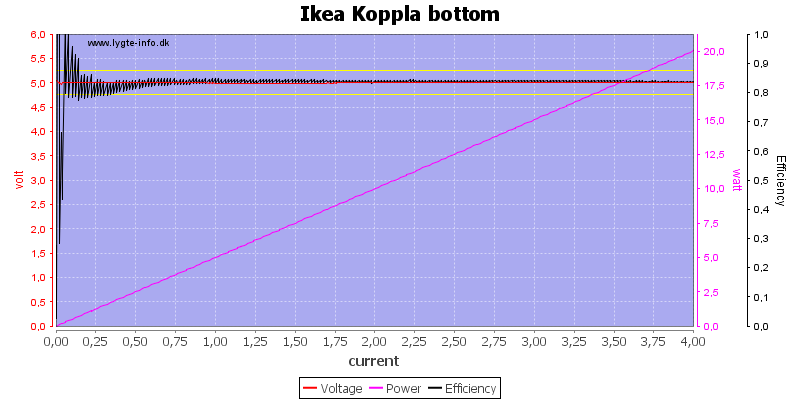
The top and bottom ports looks nearly the same, the bottom port has higher voltage when loaded.
There is no individual port protection and 4A in a usb port is a bit much.
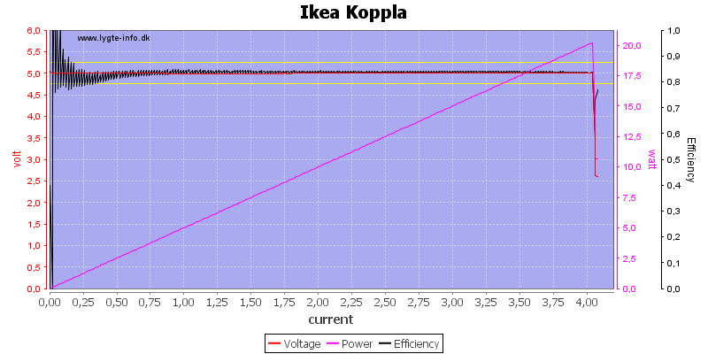
Running all port in parallel I found out the common protection trips just above 4A.
The temperature photos below are taken between 30 minutes and 60 minutes into the one hour test.
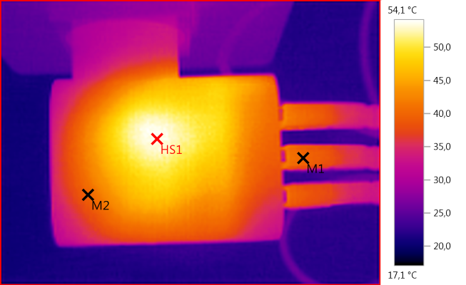
M1: 40,1°C, M2: 40,0°C, HS1: 54,1°C
The transformer is the hottest part in the charger.
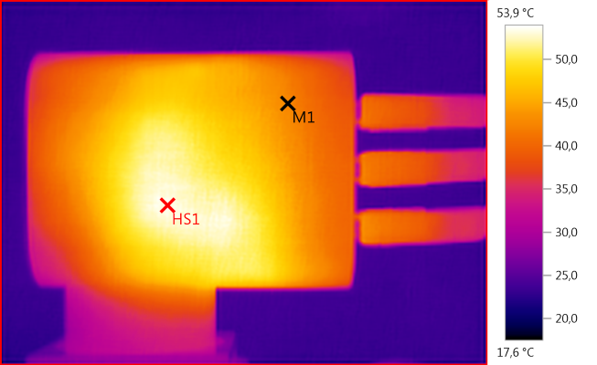
M1: 42,6°C, HS1: 53,9°C
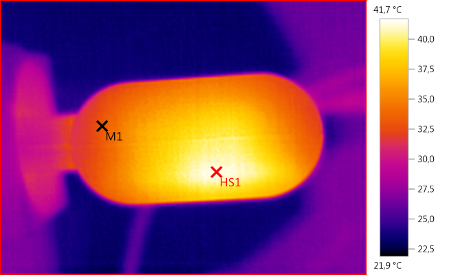
M1: 33,1°C, HS1: 41,7°C
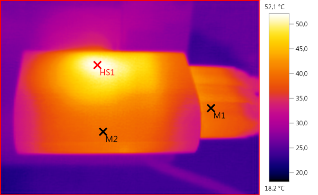
M1: 39,2°C, M2: 39,6°C, HS1: 52,1°C
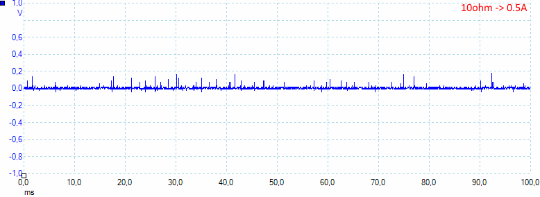
The noise level is fairly low 12mV rms and 278mVpp.
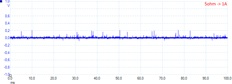
Increasing current, do increase it slightly: 16mV rms and 309mVpp.
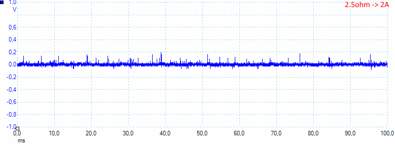
And again: 22mV rms and 313mVpp.
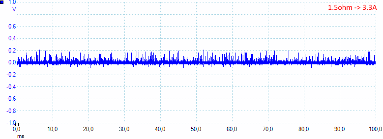
At full power the noise level is still reasonable: 30mV rms and 348mVpp.
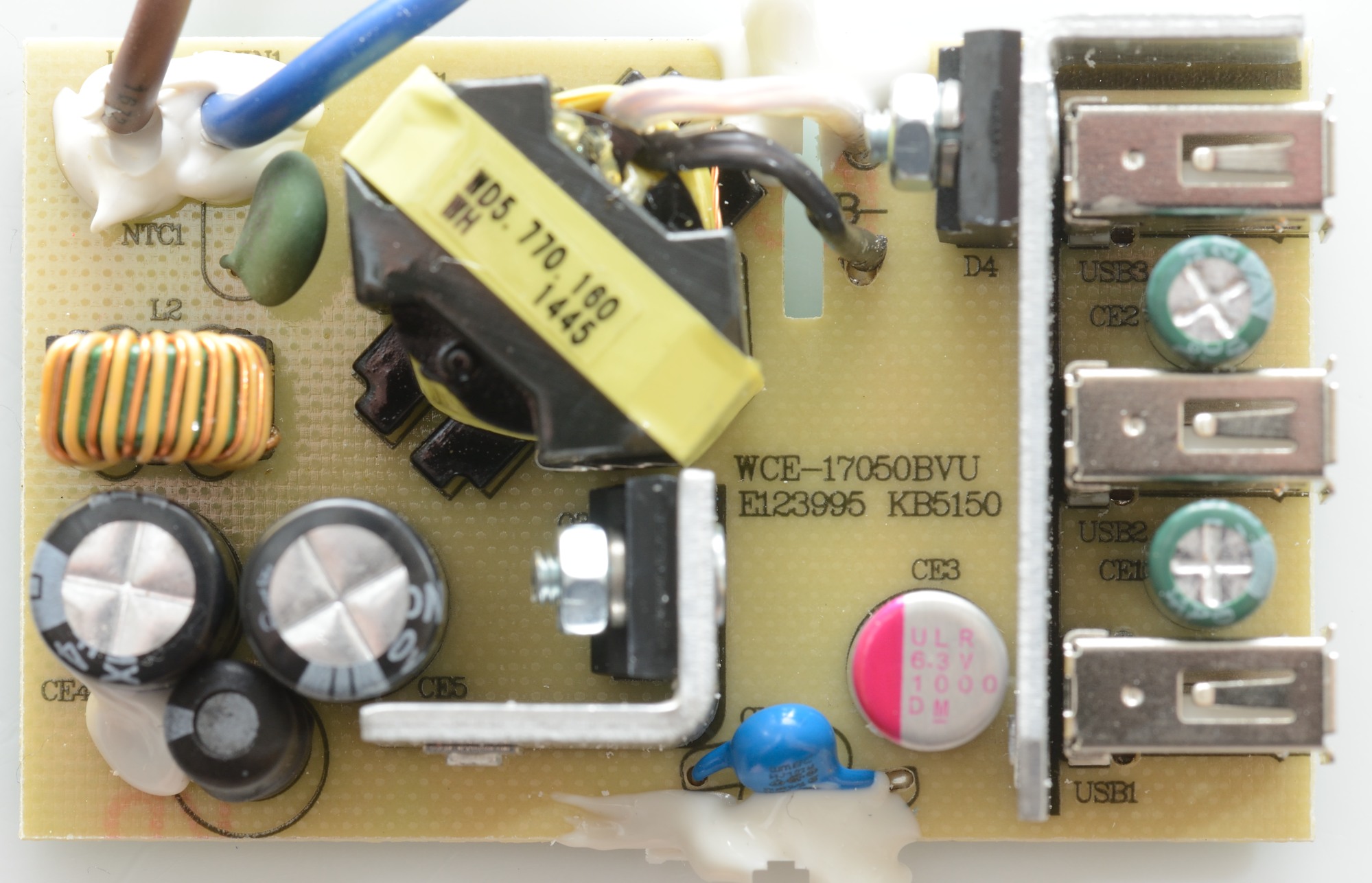
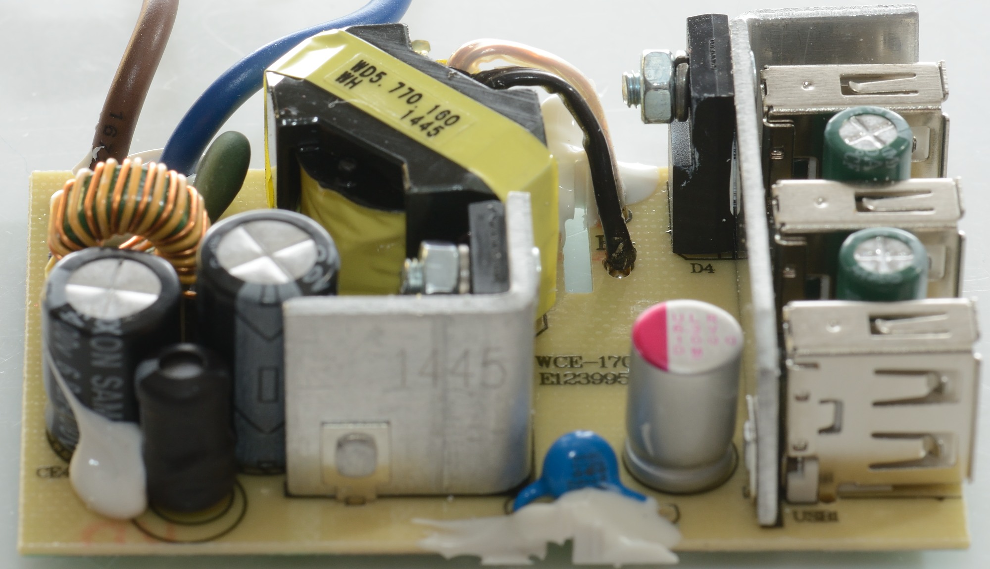
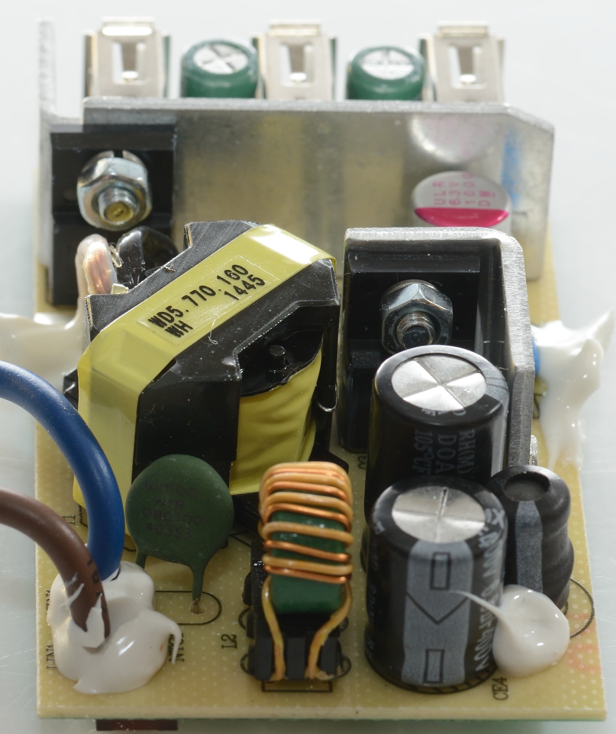
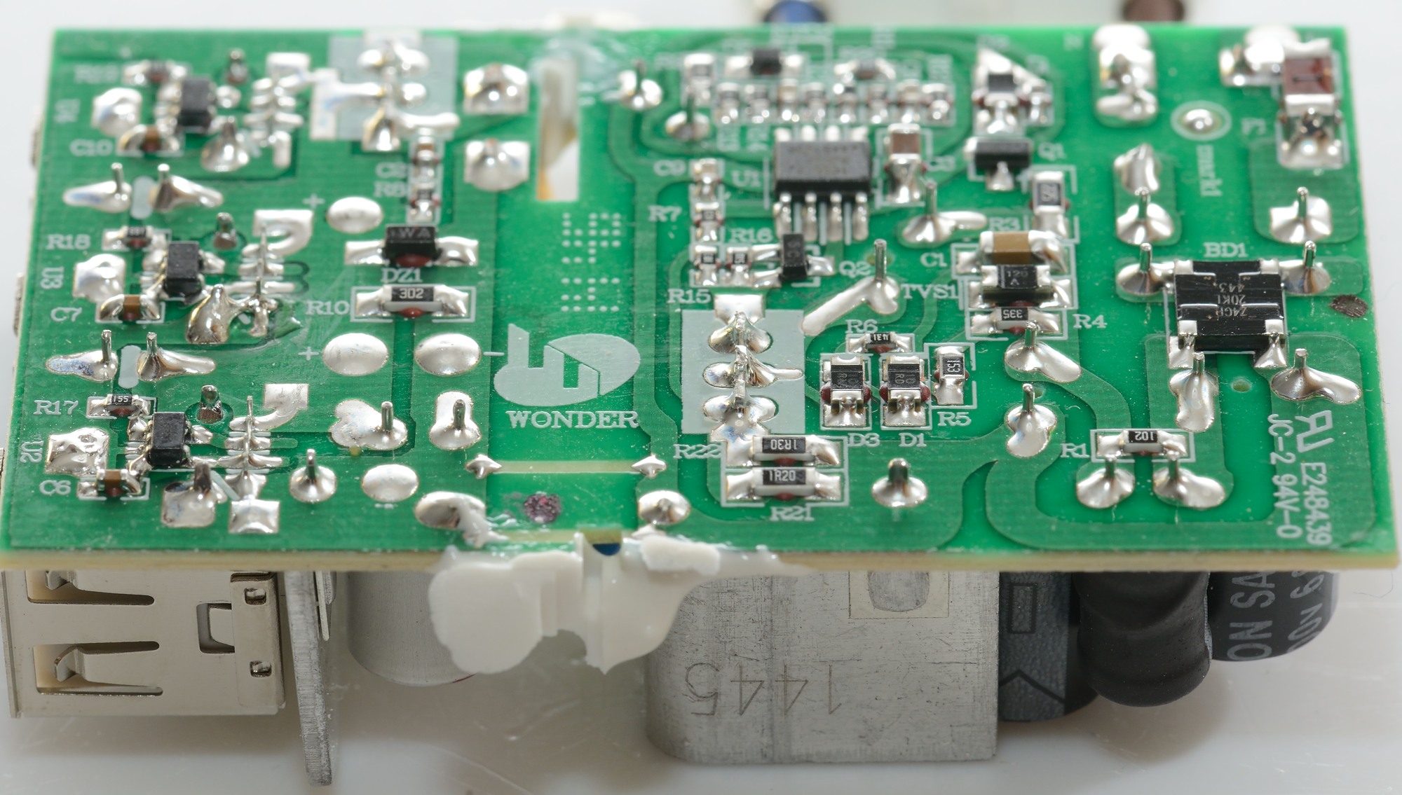
Tear down
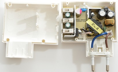
A good squeeze with a vice and a screwdriver could break it open.

There is a common mode coil on the input and a inductor between the two capacitors. It uses a mains switcher transistor and has a safety capacitor to the low volt side.
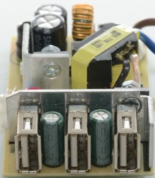
The rectifier diode uses the aluminium behind the usb connectors as heatsink.
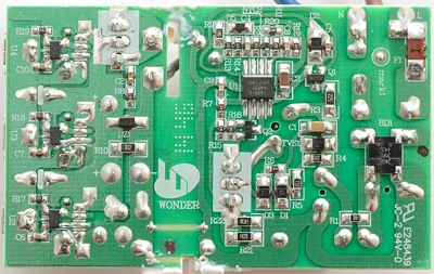
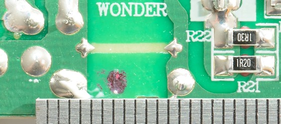
On the bottom side is the input fuse (red part marked F1), a bridge rectifier (BD1), the switcher controller (U1). Notice a part marked NTC2, it is probably a over temperature shutdown.
On the low volt side is the 3 auto coding chips (U2, U3 and U4).

The black part between the two capacitors is a inductor.
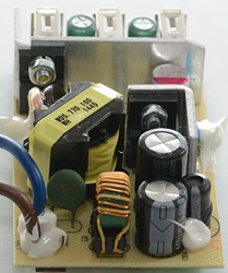
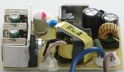
The low voltage winding on the transformer comes out at the top and goes to the other side of the slit in the circuit board. This is a way to keep good isolation distance.

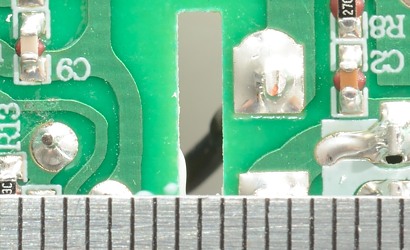
Both with a without slit there is a good safety distance.
Testing with 2500 volt and 5000 volt between mains and low volt side, did not show any safety problems.
Conclusion
It looks like a very clean design, no parts on top of each other or squeezed together, there is space for everything, including a good isolation distance. The performance is good.
Notes
Index of all tested USB power supplies/chargers
Read more about how I test USB power supplies/charger